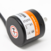
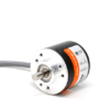
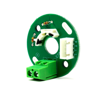
A rotary encoder is a type of position sensor which is used for determining the angular position of a rotating shaft. It generates an electrical signal, either analog or digital, according to the rotational movement.
This is a 400 PPR resolution optical encoder with quadrature outputs for increment counting. It will give 1600 transitions per rotation between outputs A and B. A quadrature decoder is required to convert the pulses to an up count. The Encoder is build to Industrial grade.
The Encoder comes with Standard 1.5 m cable length which can be extended with extra cable if needed.
-
Note:
- Consider Adding Pull up resistor to both A and B phase of the encoder output to avoid the effect of interference in output and get the precise logical output value from encoder
- Also adding pull up resistor to all phase output line protects the open collector output-triode from damage due to direct Vcc supply short circuit.
Power and Input Terminal Assignments:
| Terminal Name | Wire Color | Description |
| Phase A | White | Quadrature encoded output A |
| Phase B | Green | Quadrature encoded output B |
| VCC | Red | VCC should be connected to +ve 5V of supply |
| GND | Black | Ground should be connected to negative of supply |
| Shield | Golden | Shield should be connected to GND |
Shielding is important. At minimum, the cable should be protected either by a foil jacket with a drain wire or by a braided-wire shield that is grounded. For very sensitive applications or high-EMI environments, foil jacketed wires in combination with an overall braided-wire shield around the cable should be used to avoid the interference and precise encoder output.
Output: NPN open collector
Features :
- High cost-efficient advantages.
- Incremental rotary encoder internal adopts ASIC devices
- High reliability, long life
- Anti-jamming performance
- Small size, lightweight, compact structure
- Easy installation
- Stainless steel shaft, High resolution, High quality, line interface with waterproof protection
Tutorial Code:
|
1
2
3
4
5
6
7
8
9
10
11
12
13
14
15
16
17
18
19
20
21
22
23
24
25
26
27
28
29
30
31
32
33
34
35
36
37
38
39
40
41
42
43
44
45
46
47
48
|
//these pins can not be changed 2/3 are special pins
int encoderPin1 = 2;
int encoderPin2 = 3;
volatile int lastEncoded = 0;
volatile long encoderValue = 0;
long lastencoderValue = 0;
int lastMSB = 0;
int lastLSB = 0;
void setup() {
Serial.begin (9600);
pinMode(encoderPin1, INPUT);
pinMode(encoderPin2, INPUT);
digitalWrite(encoderPin1, HIGH); //turn pullup resistor on
digitalWrite(encoderPin2, HIGH); //turn pullup resistor on
//call updateEncoder() when any high/low changed seen
//on interrupt 0 (pin 2), or interrupt 1 (pin 3)
attachInterrupt(0, updateEncoder, CHANGE);
attachInterrupt(1, updateEncoder, CHANGE);
}
void loop(){
//Do stuff here
Serial.println(encoderValue);
delay(1000); //just here to slow down the output, and show it will work even during a delay
}
void updateEncoder(){
int MSB = digitalRead(encoderPin1); //MSB = most significant bit
int LSB = digitalRead(encoderPin2); //LSB = least significant bit
int encoded = (MSB << 1) |LSB; //converting the 2 pin value to single number
int sum = (lastEncoded << 2) | encoded; //adding it to the previous encoded value
if(sum == 0b1101 || sum == 0b0100 || sum == 0b0010 || sum == 0b1011) encoderValue ++;
if(sum == 0b1110 || sum == 0b0111 || sum == 0b0001 || sum == 0b1000) encoderValue —;
lastEncoded = encoded; //store this value for next time
}
|
Package Includes :
1 x Orange 400 PPR 2-Phase Incremental Optical Rotary Encoder
4 x 4.7KΩ Resistors for pull-ups
1 x Mounting Screw Set


There are no reviews yet.